
A Multi-Attribute Fusion Method for Digitizing Infrared Thermal Characteristics of Power Equipment
-
摘要: 本文针对电力设备红外图像诊断中热故障特征提取和数字化表达难题,提出一种多属性融合的电力设备红外热特征数字化方法。通过对电力设备热故障特性和相关诊断文件研究分析,在对图像预处理的基础上,提取图像中关键发热区域的热点温度、热点温差、发热面积、位置信息以及热点群聚现象等热属性值,构建多属性信息融合的过热性故障特征值向量,实现热故障特征数字化描述。以断路器为例对该方法进行了验证分析,结果表明,该方法对典型红外故障图谱具有良好的描述能力,可用于后续大量复杂故障样本情况下的设备热故障智能分类与诊断应用中。Abstract: Aiming at the complex problem of thermal fault feature extraction and digital representation in the infrared image diagnosis of power equipment, a multi-attribute fusion thermal feature digitization method for power equipment is proposed in this study. The method uses heat power equipment fault features and diagnostic files related to research analysis, based on image preprocessing, to extract the images of key areas with high temperatures, heating area, location, and thermal property values, such as hot clustering, building a multiple-attribute information fusion of overheating fault feature vectors to realize a digital description of the thermal fault characteristics. A circuit breaker is used as an example to verify and analyze the proposed method. The results show that the proposed method can effectively describe the typical infrared fault spectrum, and can be used in the intelligent classification and diagnosis of equipment faults in the case of a large number of complex fault samples.
-
Keywords:
- multi-attribute fusion /
- feature extraction /
- eigen vector /
- digital description
-
0. 引言
在沿海机场往往会面临机场跑道方向上时有货轮经过附近海域或大型海上平台在航线方向海上作业影响飞机起飞降安全的情况,由于机场位于开阔水域,往来船舶等频繁,发生跑道入侵事件的风险很大[1];在内陆江河或沿海航道上同样会面临过往船只过高对跨江或跨海大桥产生安全威胁的情况,需要预防桥梁受到船舶撞击[2]。为此这些地方往往需要对过往船只的高度乃至位置进行监测,实时掌握目标航向和目标高度以便评估其威胁程度。
在船舶移动的过程中由于多普勒效应影响,同时雷达引导上传目标数据周期性长、实时性差,单纯的雷达探测只能获取滞后的目标绝对位置信息,不可避免会产生一定的误差[3-4],无法掌握目标准确的高度,且随着水位的涨落,同一型船只在不同的时间经过同一位置也难以保证船只最高点的高程保持不变,为此需要一种高精度目标定位系统能够实时解算出目标的绝对位置和高程信息。
为此,本文设计了一种集成有高清可见光相机、红外热像仪、高精度激光测距机、倾角仪、光电编码器于一体的光电船只目标定位系统。
1. 测量原理
光电船只目标定位系统安装于陆地基座上,依靠内部集成的高清可见光相机、红外热像仪及激光测距机可实现昼夜对目标船只位置和高程信息的监测,下文图中云台均以PTZ代表,系统工作示意图如图 1所示。
通过北斗定位装置获取云台自身的经纬度高程坐标信息(本文中经纬度高程坐标信息均基于2000国家大地坐标系),通过激光测距机和云台编码器获取目标相对于云台的相对坐标信息,通过倾角仪获取云台安装基座姿态变化信息以对目标解算位置进行实时修正。以上信息经云台内部目标定位解算模块解算,给出目标的绝对位置信息,如图 2所示。
由于系统设备安装方式为陆基安装,故只需在系统安装完毕后,利用北斗定位装置对光电系统安装位置进行一次自身坐标位置标定,以获取光电系统的经纬度坐标和高程信息。同时利用云台内部的水平向和高低向光电编码器获取目标相对于云台的角度信息,通过激光测距机获取目标相对于云台的测量距离,由此可解算出目标对于光电系统的相对位置和高程信息,再结合光电系统自身的大地坐标位置即可解算出目标的绝对位置和高程信息,目标与云台坐标系关系如图 3所示。
![]() 图 3 目标与云台坐标系关系Figure 3. The relationship between the target and PTZ coordinate system
图 3 目标与云台坐标系关系Figure 3. The relationship between the target and PTZ coordinate system目标相对于云台坐标系的相对位置信息为:
$$ \left[ {\begin{array}{*{20}{c}} {{x_1}} \\ {{y_1}} \\ {{z_1}} \end{array}} \right] = \left[ {\begin{array}{*{20}{c}} {d\cos a\sin b} \\ {d\cos a\cos b} \\ {d\sin a} \end{array}} \right] $$ (1) 式中:x1、y1、z1为目标在云台坐标系内的坐标信息;d为目标相对云台的直线距离;a为目标相对于云台的俯仰角;b为目标相对于云台的方位角。
实际应用中,云台所处的安装基座一般要高出地面或者建筑物一定高度,长期受到大风或者振动影响后基座面相对于初始安装时往往会发生一定的姿态改变,这会造成目标相对于云台自身的相对位置也会发生轻微变化,进而一定程度上会影响对目标的定位解算精度。因此引入云台内倾角仪输出的姿态信息对云台姿态进行校正。目标与发生偏移后云台坐标系关系如图 4所示。
![]() 图 4 目标与偏移后的云台坐标系关系Figure 4. The relationship between the target and offset PTZ coordinate system
图 4 目标与偏移后的云台坐标系关系Figure 4. The relationship between the target and offset PTZ coordinate system目标在偏移后的云台坐标系的绝对位置信息为:
$$ \left[ {\begin{array}{*{20}{c}} {{x_2}} \\ {{y_2}} \\ {{z_2}} \end{array}} \right] = {\mathit{\boldsymbol{C}}}\left[ {\begin{array}{*{20}{c}} {{x_1}} \\ {{y_1}} \\ {{z_1}} \end{array}} \right] + \left[ {\begin{array}{*{20}{c}} {{x_0}} \\ {{y_0}} \\ {{z_0}} \end{array}} \right] $$ (2) 式中:x0、y0、z0为在大地坐标系下三轴的坐标;x2、y2、z2为在大地坐标系下三轴的坐标;α、β、δ分别为偏移后的云台坐标系各轴相对于原坐标系各轴的姿态变化角度,矩阵C为:
$$ {\mathit{\boldsymbol{C}}} = \left[ {\begin{array}{*{20}{c}} {\cos \delta \cos \beta }&{\sin \alpha \sin \delta \cos \beta - \cos \alpha \sin \beta }&{\cos \alpha \sin \delta \cos \beta + \sin \alpha \sin \beta } \\ {\cos \beta }&{\sin \alpha \sin \delta \sin \beta + \cos \alpha \sin \beta }&{\cos \alpha \sin \delta \cos \beta - \sin \alpha \cos \beta } \\ { - \sin \delta }&{\sin \alpha \cos \delta }&{\cos \alpha \cos \delta } \end{array}} \right] $$ (3) 2. 云台伺服系统设计
云台伺服系统采用经典的位置环、速度环、电流环三环设计,通过位置环结合速度环和电流环实现云台根据雷达系统引导信息调转到指定位置,由于雷达引导坐标位置精确性较差且具有滞后性,需要进一步优化工作流程才能锁定测量目标。因此云台在接收雷达引导信息调转到位后,转入识别跟踪流程,识别并锁定跟踪目标船只最高点,并对其进行目标定位测量解算。伺服系统控制方案如图 5所示。
其中位置环和电流环采用Proportional integral比例积分控制器,速度环采用Linear active disturbance rejection control线性自抗扰控制器。
自抗扰控制由韩京清教授最早提出,通过跟踪-微分器、反馈控制律、扩张状态观测器组成的控制器不依赖于系统的精确数学模型具有良好的鲁棒性和适应性[5]。针对自抗扰控制中非线性结构多、待调控制参数多的不便于工程化使用情况,高志强教授进一步提出了待调参数数量简化的线性自抗扰控制算法即LADRC,使整定参数和带宽相关,整定难度简化,更适合应用于工程领域[6]。
云台采用表贴式永磁同步电机,电机转矩和运动方程为:
$$ \left\{ \begin{array}{l} {T_{\rm{e}}} = {T_{\rm{L}}} + B\omega + J\frac{{{\rm{d}}\omega }}{{{\rm{d}}t}} \hfill \\ {T_{\rm{e}}} = {C_{\rm{t}}}{i_{\rm{q}}} \hfill \end{array} \right. $$ (4) 式中:Te为电磁转矩;TL为负载转矩;B为阻尼系数;ω为电机机械角速度;J为转动惯量;Ct为转矩系数;iq为转矩电流分量。
根据电机转矩和运动方程可见,速度环适宜使用一阶LADRC速度控制器,首先设计扩张状态观测器部分。
由式(4)可以进一步得到状态方程:
$$ \left\{ \begin{array}{l} {{\dot x}_1} = {x_2} + {l_0}{i_{\rm{q}}} \hfill \\ {x_2} = f \hfill \end{array} \right. $$ (5) 式中:x1=ω为电机机械角速度;x2为$ f = \frac{1}{J}({C_t}{i_{\rm{q}}} - {T_{\rm{L}}} - B\omega ) - l{}_0{i_{\rm{q}}} $,为未知待观测量;l0为速度环LADRC控制器待调参数。
采用的线性状态观测器方程为:
$$ \left\{ \begin{array}{l} \dot z = {\mathit{\boldsymbol{A}}}z + {\mathit{\boldsymbol{B}}}u + {\mathit{\boldsymbol{L}}}({x_1} - {z_1}) \hfill \\ {\mathit{\boldsymbol{A}}} = \left[ {\begin{array}{*{20}{c}} 0&1 \\ 0&0 \end{array}} \right] \hfill \\ {\mathit{\boldsymbol{B}}} = \left[ {\begin{array}{*{20}{c}} {{l_0}} \\ 0 \end{array}} \right] \hfill \\ {\mathit{\boldsymbol{L}}} = \left[ {\begin{array}{*{20}{c}} {{l_1}} \\ {{l_2}} \end{array}} \right] \hfill \end{array} \right. $$ (6) 式中:z为系统观测的状态量;x为系统实际的状态量;u为系统输入量。
由式(5)、式(6)可以得到:
$$ \left\{ \begin{array}{l} \dot {\hat \omega} = \hat f + {l_0}{i_{\rm{q}}} + {l_1}(\omega - \hat \omega ) \hfill \\ \hat f = {l_2}(\omega - \hat \omega ) \hfill \end{array} \right. $$ (7) 式中:$ \hat \omega $为电机角速度观测值;$ \hat f $为待观测量f的观测值。
取$ {l_0}{i_q} = {u_0} - \hat f $,当$ \hat f $无限接近于f时,则由式(5)有:
$$ \dot \omega = f + ({u_0} - \hat f) = {u_0} $$ (8) 式中:u0为控制律输出量。
电机速度环经过控制器可等效为一阶积分环节,故LADRC控制律环节可简化设计为比例控制器[7],取$ {u_0} = {K_{\rm{p}}}({\omega _{{\rm{ref}}}} - \hat \omega ) $,ωref为速度环给定转速。云台采用的力矩电机为低速电机且长期工作于低速运行状态,故省去LADRC中的跟踪-微分器环节设计,由此可以得到速度环LADRC控制器结构如图 6所示。
系统中俯仰向采用J180LWX005型无刷力矩电机和EAC90F-0M21S型光电编码器,采用的电机和编码器参数如表 1所示。
表 1 电机和编码器参数Table 1. Motor and encoder parameterJ180LWX005 motor Value EAC90F-0M21S encoder Value Rated torque/(N⋅m) 8 Resolution 21 bits Rated current/A 4 Accuracy < 30″ No-load speed/rpm 110 Maximum speed/rpm 6000 Torque coefficient/(N⋅m/A) 2 Phase resistor/Ω 1.6 Phase inductance/mH 4.5 速度环给定转速ωref=3.66°/s,分别测试速度环采用PI控制器和LADRC控制器速度响应情况,并在速度达到稳定后突加一固定干扰力矩,速度环响应曲线如图 7所示。
由图 7、图 8可见采用LADRC控制器后,云台速度环可更快抑制扰动,转速控制波动量小更加平稳,位置调转响应更快。
位置闭环响应曲线如图 8所示,电机初始位置为30°,测试时先回到0°位置,再调转至50°位置。
3. 系统软件设计
该目标定位系统工作流程如图 9所示。云台根据雷达引导信息调转至指定位置,由于雷达引导位置存在一定误差,加上目标船只处于移动状态因此雷达引导信息具有滞后性,且雷达不能获取到目标最高点位置,因此云台调转到位后不能立刻进行目标船只定位测高,需要先识别选定视场内目标船只最高点,然后再开启跟踪锁定目标船只最高点进行定位测高。
在得到目标船只测距值后,通过依次读取云台倾角仪获取云台相对大地坐标系姿态角、云台编码器值获取目标船只相对云台坐标系极坐标,结合云台所处的经纬度高程信息,即可解算出目标船只准确的经纬度和高程信息。
4. 测试结果
随机选取了4个不同方向不同距离的目标点对系统的测量精度进行测试,目标点经纬度测试情况如表 2所示。
表 2 目标经纬度测量对照Table 2. Target longitude and latitude measurement comparisonActual value of target longitude and latitude/° Measurement value of target longitude and latitude/° Distance/m Deviation/m Longitude: 118.7693622; Latitude: 31.87598539 Longitude: 118.7693379; Latitude: 31.8759465 2638 4.77 Longitude: 118.7841865; Latitude: 31.896963 Longitude: 118.7841426; Latitude: 31.8969342 3825 4.86 Longitude: 118.7775752; Latitude: 31.9166531 Longitude: 118.777571; Latitude: 31.9166863 6025 3.71 Longitude: 118.86845383; Latitude: 31.89987727 Longitude: 118.868425; Latitude: 31.8998692 8224 2.84 目标点高程测试情况,如表 3所示。综合表 2和表 3可见,该系统对目标点在经纬度测量上误差不超过5 m,高程测量上误差不超过2 m,可实现较高的测量精度。
表 3 目标高程测量对照Table 3. Target height measurement comparisonActual value of target height/m Measurement value/m Distance/m Deviation/m 87.944 88.2 2638 0.256 113.346 112.4 3825 -0.946 116.26 115.2 6025 -1.06 230.2 228.7 8224 -1.5 5. 结束语
文中提出了一种光电式高精度目标船只定位系统,利用该系统可获取较高精度的目标位置和高程信息,有效提高了目标定位测算的准确度和效率。
试验表明了该设计的合理性。试验结果证明该系统可给出目标位置较高精度的定位数据,投入使用后工作稳定可靠,具有良好的性能,在无人值守监控定位领域具有广泛的应用前景。
-
![]()
图 1 多属性信息融合特征算法流程图
Figure 1. Flow chart of multi-attribute information fusion feature algorithm
![]()
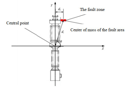
图 6 分割故障区域及查找等效热源点
Figure 6. Segment the fault area and find the equivalent heat source
表 1 各区域的T1与T2对比表
Table 1 Comparison table of T1 and T2 for each region
Value of simulation Measured value Phase sequence Area g T1/℃ T3/℃ T2/℃ g T1/℃ T3/℃ T2/℃ a Superior 53 3.8 2.6 1.2 53 3.8 2.6 1.2 Centre 70 8.5 5.9 70 8.4 5.8 Below 48 2.6 0 48 2.6 0 b Superior 61 6.1 3.8 2.3 62 6.2 3.7 2.5 Centre 213 46.6 42.8 213 46.5 42.8 Below 53 3.8 0 52 3.7 0 c Superior 68 8.0 3.5 4.5 68 7.9 3.5 3.4 Centre 255 57.8 54.3 255 57.8 54.3 Below 51 3.5 0 51 3.5 0  下载: 导出CSV
表 2 断路器故障等级判断标准
Table 2 Criteria for fault grade judgment of circuit breaker
Failure level Common defect Serious defects Critical defect Failure criterion/℃ 0<T<55 55≤T≤80 T>80
下载: 导出CSV
表 3 部分电力设备热故障特征提取结果
Table 3 Thermal fault feature extraction results of powerequipment
Amount T1 T2 Si L M 1 48.5 45 0.008 [1.3,80,38] 2 42.8 38.3 0.001 [1.3,38.2,21.14] 2 50.6 28.3 0.009 [0.14,75,24.67] 1 ⋮ ⋮ ⋮ ⋮ ⋮ ⋮ 149 46.5 42.8 0.009 [1.4,-47,51] 2 150 57.8 54.3 0.01 [1.3,-63,58]
下载: 导出CSV
-
[1] 邹辉, 黄福珍. 基于FAsT-Match算法的电力设备红外图像分割[J]. 红外技术, 2016, 38(1): 21-27. http://hwjs.nvir.cn/article/id/hwjs201601004 ZOU Hui, HUANG Fuzhen. Infrared image segmentation of power equipment based on fast-match algorithm[J]. Infrared Technology, 2016, 38(1): 21-27. http://hwjs.nvir.cn/article/id/hwjs201601004
[2] 张恒源. 基于红外图像处理的变电站设备故障诊断方法研究[D]. 长春: 长春工业大学, 2019. ZHANG Hengyuan. Research on substation equipment fault diagnosis method based on infrared image processing[D]. Changchun: Changchun University of Technology, 2019.
[3] 余彬, 万燕珍, 陈思超, 等. 基于密度相似因子的电力红外图像分割方法[J]. 红外技术, 2017, 39(12): 1139-1143. http://hwjs.nvir.cn/article/id/hwjs201712012 YU Bin, WAN Yanzhen, CHEN Sichao, et al. Power infrared image segmentation based on density similarity factor[J]. Infrared Technology, 2017, 39(12): 1139-1143. http://hwjs.nvir.cn/article/id/hwjs201712012
[4] 腾云, 陈双, 邓洁清, 等. 智能巡检机器人系统在苏通GIL综合管廊工程中的应用[J]. 高电压技术, 2019, 45(2): 393-401. https://www.cnki.com.cn/Article/CJFDTOTAL-GDYJ201902006.htm TENG Yun, CHEN Shuang, DENG Jieqing, et al. Application of intelligent inspection robot system in Sutong GIL Integrated Pipe Gallery Project[J]. High Voltage Technology, 2019, 45(2): 393-401. https://www.cnki.com.cn/Article/CJFDTOTAL-GDYJ201902006.htm
[5] 王有元, 李后英, 梁玄鸿, 等. 基于红外图像的变电设备热缺陷自调整残差网络诊断模型[J]. 高电压技术, 2020, 46(9): 3000-3007. https://www.cnki.com.cn/Article/CJFDTOTAL-GDYJ202009002.htm WANG Youyuan, LI Houying, LIANG Xuanhong, et al. Self-adjusting residual network diagnosis model for thermal defects of transformer equipment based on infrared image[J]. High Voltage Technology, 2020, 46(9): 3000-3007. https://www.cnki.com.cn/Article/CJFDTOTAL-GDYJ202009002.htm
[6] 王佳林, 崔昊杨, 许永鹏, 等. 基于SOM神经网络的变电站设备红外热像诊断研究[J]. 上海电力学院学报, 2016, 32(1): 78-82. https://www.cnki.com.cn/Article/CJFDTOTAL-DYXY201601017.htm WANG Jialin, CUI Haoyang, XU Yongpeng, et al. Research on infrared thermal diagnosis of substation equipment based on SOM neural network[J]. Journal of Shanghai University of Electric Power, 2016, 32(1): 78-82. https://www.cnki.com.cn/Article/CJFDTOTAL-DYXY201601017.htm
[7] 林颖, 郭志红, 陈玉峰. 基于卷积递归网络的电流互感器红外故障图像诊断[J]. 电力系统保护与控制, 2015, 43(16): 87-94. https://www.cnki.com.cn/Article/CJFDTOTAL-JDQW201516013.htm LIN Ying, GUO Zhihong, CHEN Yufeng. Infrared fault diagnosis of current transformer based on convolutional recursive network[J]. Power System Protection and Control, 2015, 43(16): 87-94. https://www.cnki.com.cn/Article/CJFDTOTAL-JDQW201516013.htm
[8] Huda ASN, Taib S. A comparative study of MLP networks using backpropagation algorithms in electrical equipment thermography[J]. Arab. J. Sci. Eng., 2014, 39: 3873-3885. DOI: 10.1007/s13369-014-0989-7
[9] ZOU H, HUANG F. A novel intelligent fault diagnosis method for electrical equipment using infrared thermography[J]. Infrared Physics & Technology, 2015, 73: 29-35. http://www.onacademic.com/detail/journal_1000038244612810_35a3.html
[10] LI B, ZHU X, ZHAO S, et al. HV power equipment diagnosis based on infrared imaging analyzing[C]//2006 International Conference on Power System Technology, IEEE, 2006: 1-4.
[11] 彭向阳, 梁福逊, 钱金菊, 等. 基于机载红外影像纹理特征的输电线路绝缘子自动定位[J]. 高电压技术, 2019, 45(3): 922-928. https://www.cnki.com.cn/Article/CJFDTOTAL-GDYJ201903033.htm PENG Xiangyang, LIANG Fuxun, QIAN Jinju, et al. Automatic location of transmission line insulator based on texture feature of airborne infrared image[J]. High Voltage Technology, 2019, 45(3): 922-928. https://www.cnki.com.cn/Article/CJFDTOTAL-GDYJ201903033.htm
[12] LIU Y, PEI S T, FU W P, et al. The discrimination method as applied to a deteriorated porcelain insulator used in transmission lines on the basis of a convolution neural network[J]. IEEE Transactions on Dielectrics and Electrical Insulation, 2017, 24(6): 3559-3566. DOI: 10.1109/TDEI.2017.006840
[13] 李佐胜, 姚建刚, 杨迎建, 等. 基于方差分析的绝缘子红外热像特征选择方法[J]. 电网技术, 2009, 33(1): 92-96. https://www.cnki.com.cn/Article/CJFDTOTAL-DWJS200901024.htm LI Zuosheng, YAO Jiangang, YANG Yingjian, et al. Infrared thermal image feature selection method of insulator based on ANOVA[J]. Power System Technology, 2009, 33(1): 92-96. https://www.cnki.com.cn/Article/CJFDTOTAL-DWJS200901024.htm
[14] 李鑫, 崔昊杨, 许永鹏, 等. 电力设备IR图像特征提取及故障诊断方法研究[J]. 激光与红外, 2018, 48(5): 659-664. https://www.cnki.com.cn/Article/CJFDTOTAL-JGHW201805023.htm LI Xin, CUI Haoyang, XU Yongpeng, et al. Research on power equipment IR image feature extraction and fault diagnosis method[J]. Laser & Infrared, 2018, 48(5): 659-664. https://www.cnki.com.cn/Article/CJFDTOTAL-JGHW201805023.htm
[15] 熊芬芳. 基于图像处理技术的电气设备故障诊断方法研究[D]. 上海: 东华大学, 2015. XIONG Fenfang. Study on fault diagnosis method of electrical equipment based on image processing technology[D]. Shanghai: Donghua University, 2015.
[16] 王旭红, 李浩, 樊绍胜, 等. 基于改进SSD的电力设备红外图像异常自动检测方法[J]. 电工技术学报, 2020, 35(S1): 302-310. https://www.cnki.com.cn/Article/CJFDTOTAL-DGJS2020S1034.htm WANG Xuhong, LI Hao, FAN Shaosheng, et al. Automatic abnormal detection method of infrared image of power equipment based on improved SSD[J]. Transactions of China Electrotechnical Society, 2020, 35(S1): 302-310. https://www.cnki.com.cn/Article/CJFDTOTAL-DGJS2020S1034.htm
[17] 张晓霞. 变电站电压致热型设备的红外测温诊断[J]. 科技信息, 2010(25): 757-758. https://www.cnki.com.cn/Article/CJFDTOTAL-KJXX201025603.htm ZHANG Xiaoxia. Infrared temperature diagnosis of voltage heating equipment in substation[J]. Science and Technology Information, 2010(25): 757-758. https://www.cnki.com.cn/Article/CJFDTOTAL-KJXX201025603.htm
[18] 唐佳能, 金鑫, 张建志, 等. DL/T 664—2016《带电设备红外诊断应用规范》的应用分析[J]. 智能电网, 2017, 5(9): 924-928. https://www.cnki.com.cn/Article/CJFDTOTAL-ZNDW201709016.htm TANG Jianeng, JIN Xin, ZHANG Jianzhi, et al. Application analysis of DL/T 664-2016 infrared diagnosis application specification for live equipment[J]. Smart Power Grid, 2017, 5(9): 924-928. https://www.cnki.com.cn/Article/CJFDTOTAL-ZNDW201709016.htm
[19] 王旭红, 李浩, 樊绍胜, 等. 基于改进SSD的电力设备红外图像异常自动检测方法[J]. 电工技术学报, 2020, 35(S1): 302-310. https://www.cnki.com.cn/Article/CJFDTOTAL-DGJS2020S1034.htm WANG Xuhong, LI Hao, FAN Shaosheng, et al. Automatic abnormal detection method of infrared image of power equipment based on improved SSD[J]. Transactions of China Electrotechnical Society, 2020, 35(S1): 302-310. https://www.cnki.com.cn/Article/CJFDTOTAL-DGJS2020S1034.htm
[20] 王小芳, 毛华敏. 一种复杂背景下的电力设备红外图像分割方法[J]. 红外技术, 2019, 41(12): 1111-1116. http://hwjs.nvir.cn/article/id/hwjs201912004 WANG Xiaofang, MAO Huamin. Infrared Image Segmentation Method for Power Equipment under Complex Background[J]. Infrared Technology, 2019, 41(12): 1111-1116. http://hwjs.nvir.cn/article/id/hwjs201912004
[21] 王小芳, 康琛, 程宏波, 等. 基于红外图像处理的变电设备热故障自动诊断方法[J]. 华东交通大学学报, 2019, 36(3): 111-118. https://www.cnki.com.cn/Article/CJFDTOTAL-HDJT201903015.htm WANG Xiaofang, KANG Chen, CHENG Hongbo, et al. Automatic thermal fault diagnosis method of substation equipment based on infrared image processing[J]. Journal of East China Jiaotong University, 2019, 36(3): 111-118. https://www.cnki.com.cn/Article/CJFDTOTAL-HDJT201903015.htm
[22] 许晓路, 周文, 周东国, 等. 基于PCNN分层聚类迭代的故障区域自动提取方法[J]. 红外技术, 2020, 42(8): 809-814. http://hwjs.nvir.cn/article/id/hwjs202008017 XU Xiaolu, ZHOU Wen, ZHOU Dongguo, et al. Automatic fault area extraction method based on PCNN hierarchical clustering iteration[J]. Infrared Technology, 2020, 42(8): 809-814. http://hwjs.nvir.cn/article/id/hwjs202008017
-
期刊类型引用(1)
1. 李绍军,李英杰,李威,徐哲,王国右,徐妍,荆凡胜. 车载升降式光电云台共振抑制方法研究. 红外技术. 2024(04): 406-412 .  本站查看
本站查看
其他类型引用(0)


计量
- 文章访问数: 124
- HTML全文浏览量: 32
- PDF下载量: 27
- 被引次数: 1
